Selecting the right enclosure design service helps reduce redesign risks, prevent unnecessary tooling changes, and create a smoother transition from prototype development to production. When mechanical housing development is separated from PCB design, teams often encounter fitment issues, connector misalignment, and assembly problems that require costly redesign before production.
This guide explains how professional enclosure design services combine engineering requirements, production-ready CAD, and manufacturing considerations to create reliable custom housings for electronic equipment. We evaluate nominal wall thicknesses, ECAD-MCAD clearance constraints, and material tolerances to ensure your housing scales without structural or regulatory failures.
Enclosure Design Services and Project Requirements
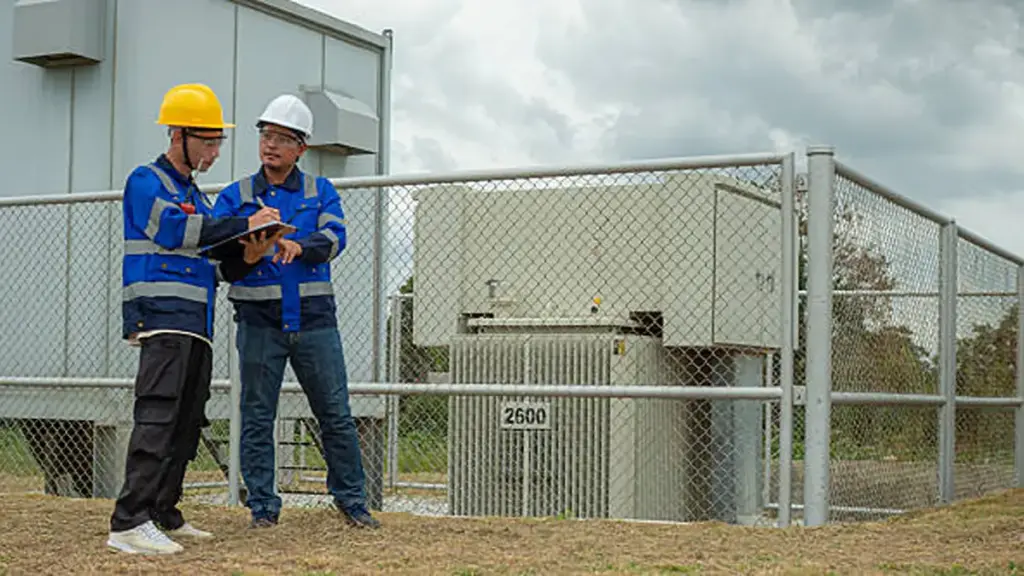
Successful electronic enclosure design requires parallel development of mechanical housing and internal circuitry to guarantee proper fit, heat dissipation, and regulatory compliance.
Engineering and Industrial Design Phases
Building a functional housing for electronic assemblies follows a strict physical progression. Developing the enclosure alongside the PCB avoids costly downstream rework and alignment failures.
- Requirements Definition: Map environmental exposure, target IP/NEMA ratings, and expected mechanical loads early in the design cycle. Understanding different NEMA enclosure types helps engineers select suitable protection levels for specific operating environments.
- Concept Development: Detail overall product form factors, footprint constraints, ergonomics, tactile usability, and brand elements.
- Detailed 3D CAD Modeling: Create precise models of internal structures, wall thicknesses, draft angles, and PCB integrations to check clearances.
- Seleção de Materiais: Select suitable metals such as carbon steel, aço inoxidável, and aluminum based on structural strength, resistência à corrosão, weight requirements, thermal performance, and application environment.
- Thermal Design: Analyze heat dissipation using passive conduction, natural convection, airflow paths, or active cooling fans and heat pipes.
- Prototipagem & Iterative Testing: Verify dimensional tolerances, drop resistance, and seal integrity with physical 3D-printed or machined samples.
Technical Requirements and Integration Specifications
Electronics packaging demands a disciplined approach to physical, electrical, and commercial constraints. Designers must isolate high-voltage systems and ensure reliable mating at every interface.
- Environmental Constraints: Address temperature operating extremes, chemical or salt spray exposure, Estabilidade UV, and specific IP/NEMA ingress protection targets.
- Elétrica & Conformidade de segurança: Establish clear grounding strategies, creepage and clearance isolation distances, and continuous EMI/RFI shielding.
- Mechanical Mating Guidelines: Define board mounting standoffs, precise connector clearances, and mounting bracket integration.
- User Interface Placement: Detail button access travel, display window visibility, indicator light guides, and service entry panels.
- Fabricação & Economic Guidelines: Align target production volumes with injection molding, sheet metal fabrication, or off-the-shelf housings to control tooling costs.
Mechanical Layout and Component Integration
Locking physical clearances and thermal paths early prevents interference and sealing failures during production ramp-up.
CAD Integration and Manufacturing Design Considerations
Designing an enclosure requires real-time coordination between electrical and mechanical databases. Developing these elements in isolation risks physical interference, board stress, and late-stage tooling changes that destroy project budgets.
- 3D Synchronization: Elétrica (ECAD) and mechanical (MCAD) tools must link directly to share 3D models of components, defining board outlines, keepout zones, and screw bosses before routing.
- Board Edge Gap: Keep a 0.5 mm to 1.0 mm perimeter clearance between the PCB edge and the inner walls to absorb manufacturing and depanelization tolerances.
- Vertical Clearance: Allow adequate space between the tallest PCB components and the enclosure cover based on component height, assembly tolerances, vibration requirements, and thermal considerations to prevent interference during operation and production.
- Port Alignment: Protrude external connectors 1.0 mm to 1.5 mm beyond the chassis wall to guarantee secure mating without inducing side-load stress.
Thermal Management and Environmental Ingress Protection
Ingress protection and thermal dissipation often pull designs in opposite directions. Selecting suitable enclosure cooling systems can help maintain operating temperatures while preserving required protection levels. Achieving high sealing ratings restricts open-air convection, making internal layout choices critical for system survivability.
- Thermal Zoning: Position high-heat parts at the top of the enclosure to leverage natural convection, keeping sensitive components in cooler, lower zones.
- Conductive Cooling: Bridge the physical gap between hot components and aluminum chassis walls using thermal interface materials (TIMs) or gap pads.
- Ingress Sealing: Integrate compression grooves for EPDM or silicone gaskets to meet target IP or NEMA ratings against dust and water.
- Electromagnetic Shielding: Select conductive enclosure materials such as aluminum or steel, and optimize grounding, seams, and bonding methods to reduce electromagnetic interference.
High-Performance Enclosures Built to Last
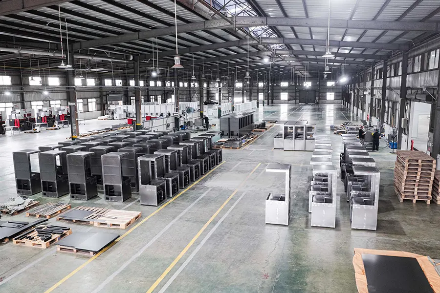
Material, Grossura, and Environmental Requirements
Aligning enclosure materials and nominal wall thicknesses to exact environmental exposure levels prevents mechanical failure, ensuring long-term field reliability and compliance.
Environmental Exposure and Material Selection Standards
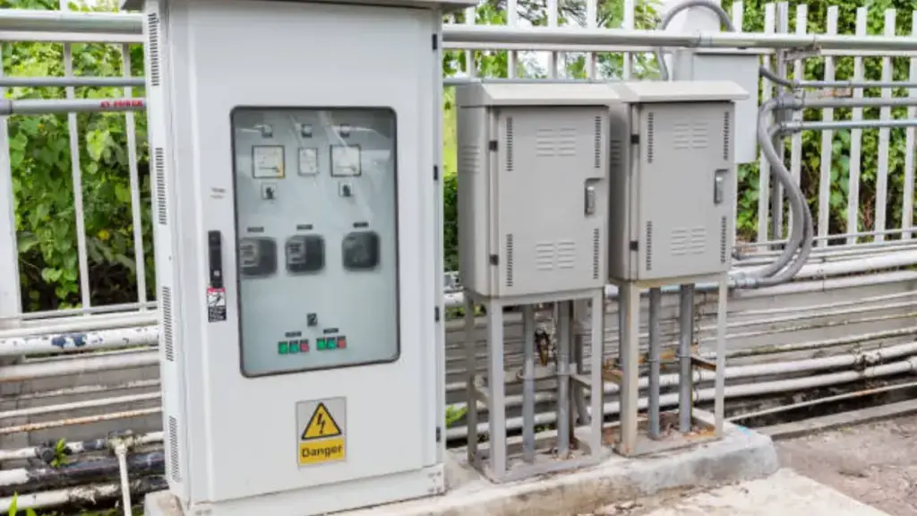
Operating environments dictate material survival. We design by identifying localized exposure risks first, converting physical hazards into precise NEMA and IP targets before laying down CAD geometry.
- NEMA and IP Ratings: We map ingress standards to specific indoor and outdoor environmental exposure risks, safeguarding electronics against dust, washdowns, and submersion.
- Aço inoxidável (SS304/SS316): These grades deliver critical corrosion resistance in chemical processing plants and highly hygienic food or pharmaceutical environments. Choosing the right sheet metal materials used for custom enclosures also depends on factors such as strength, resistência à corrosão, peso, and application requirements.
- Polycarbonate and Engineered Plastics: UV-stabilized polymers provide robust outdoor durability and high impact resistance without blocking RF signals.
Thickness Engineering and Manufacturing Process Rules
Wall thickness directly controls part quality, cycle times, and mechanical strength. Imbalanced dimensions cause warping, sink marks, and premature structural failure in the field.
- Injection-Molded Plastics: Molded enclosures require a uniform nominal wall thickness between 1.5 mm and 3.5 mm to eliminate internal cooling stress and prevent warping.
- Standoffs and Screw Bosses: High-stress fastening locations demand localized thickness increases of 3.0 mm to 4.0 mm to handle assembly loads without cracking.
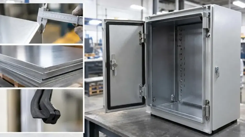
- Sheet Metal Thickness & Structural Design: We select appropriate sheet metal thickness based on enclosure dimensions, application requirements, and environmental conditions. Features such as formed bends, reinforcement ribs, and welded structures improve mechanical strength while maintaining cost-effective and manufacturable designs.
Térmico, PI, EMI, and Structural Design Factors
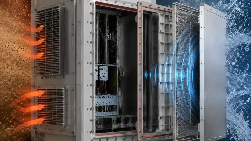
Sealed electronic enclosures must manage thermal dissipation and environmental ingress simultaneously, combining structural stiffness, electromagnetic shielding, and precise gasket compression into a single cohesive mechanical assembly.
Thermal and Environmental Ingress Protection
Sealing an enclosure to prevent dust and water ingress directly compromises its ability to vent heat. Resolving this conflict requires physical design choices that optimize thermal paths without opening entry points for contaminants.
- Passive cooling integration: Engineers incorporate external heat-dissipating fins and high-conductivity aluminum alloys into the outer shell, pulling heat away from internal electronics in fully sealed environments.
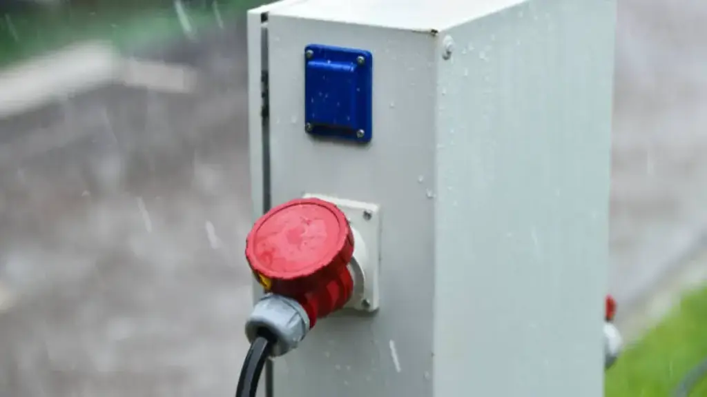
- Ingress protection seals: Continuous compression gaskets, interlocking tongue-and-groove profiles, and torque-controlled fasteners prevent water and dust entry to meet IP-rated requirements such as IP65 and IP66 applications.
- Pressure-equalizing membranes: Waterproof, breathable vent membranes prevent condensation and relieve physical stress on seals caused by internal temperature shifts during operation.
- Directional airflow paths: Strategic louvers and vent placements utilize natural or forced convection while maintaining a circuitous path that blocks water sprays and airborne debris.
Electromagnetic Shielding and Structural Integrity Integration
Heavy structural loads, high-frequency signals, and drop-vibration hazards intersect at the enclosure housing. Combining physical stiffness with robust electrical grounding avoids the weight penalty of separate internal shielding brackets.
- Conductive raw materials: Using aluminum, aço, or conductive platings on engineered plastics forms a continuous Faraday cage to block electromagnetic interference.
- Aperture control: Tight spacing of fasteners, conductive gaskets along joint seams, and honeycomb patterns on vents block radio frequency leaks while allowing airflow.
- Structural reinforcement: Molded-in stiffening ribs, gussets, and robust PCB mounting bosses prevent physical flexing under impact and maintain consistent seal pressure.
- Dual-purpose shielding plates: Internal metal shields function as both RF barriers and thermal spreaders, conducting heat directly from hot processors to the cold outer chassis.
CAD Documentation, Prototipagem, and DFM Review
Robust CAD models, physical validation, and rigorous DFM reviews convert complex electromechanical concepts into repeatable, cost-effective production realities.
| Phase | Focus Areas | Primary Deliverables |
|---|---|---|
| CAD Documentation | Board integration, component clearances, and mechanical compliance | 3D assemblies, ASME/ISO 2D drawings, engineering BOMs |
| Prototipagem & DFM | Tolerance stack-up check, physical fit checks, and manufacturer sign-off | 3D prints, CNC parts, redlined CAD, written feedback reports |
CAD Deliverables and Standardized Documentation in Enclosure Design
To bring an electronics housing to life, you must construct a single, comprehensive source of truth. The enclosure is never designed in isolation; it must lock directly onto the electronic layout from day one.
A production-ready enclosure design package typically includes:
- 3D Assembly Models: These models integrate the board outline, component height clearances, and mounting hardware alongside internal features like structural ribs and screw bosses.
- 2D Manufacturing Drawings: These ASME and ISO-compliant documents specify linear dimensions, geometric dimensioning and tolerancing (GD&T), and flat patterns for sheet metal fabrication.
- Complete Production Packages: This bundle houses the engineering bill of materials (BOM), surface finish requirements, and standardized hardware specifications.
This documentation removes guesswork on the factory floor, allowing fabricators to program CNC machinery or build injection molds without back-and-forth delays.
Prototyping Workflows and Design for Manufacturability (DFM) Integração
Moving from virtual CAD to physical hardware requires systematic validation. Physical mockups reveal fitment errors and assembly interferences that 3D software can easily miss.
Our validation workflow relies on three core execution phases:
- Iterative Prototyping: We use FDM or SLS 3D printing for quick fit-checks, CNC machining for high-precision metal components, and soft tooling to test production-grade plastics.
- Rigorous DFM Analysis: Engineers analyze process-critical rules, checking uniform wall thicknesses, draft angles for part ejection, and worst-case tolerance stack-ups around critical ports.
- Collaborative Manufacturer Sign-Off: We execute formal review cycles with your fabricator, delivering redlined CAD files, detailed written feedback, and structured inspection plans.
This transition from design validation to physical production helps identify manufacturability issues earlier and reduces unnecessary modification costs during fabrication.
Custom Metal Enclosure Design and Manufacturing Support
A production-ready enclosure requires more than accurate CAD models; it also needs manufacturing expertise to ensure the final housing meets structural, ambiental, and assembly requirements. SJE Enclosure provides integrated support from enclosure design review to custom metal enclosures fabrication, helping customers transform concepts into reliable production parts. With capabilities including laser cutting, Dobragem CNC, soldagem, surface finishing, e montagem, SJE manufactures sheet metal enclosures using materials such as carbon steel, aço inoxidável, and aluminum. The team supports OEM and ODM projects with flexible production options, including prototype development, small-batch manufacturing, and scaled production. By combining engineering communication with fabrication experience, SJE helps reduce design revisions, improve manufacturability, and deliver IP/NEMA-rated enclosures ready for real-world applications.
Preparing Your Enclosure Design for Scaled Production
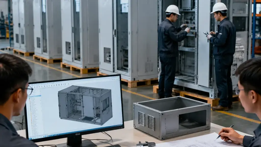
Scaling enclosure production successfully requires locking your manufacturing process, geometry rules, and internal components before releasing final tooling to fabrication partners.
Manufacturing Process Selection and DFM Geometry Rules
Select the primary manufacturing process before starting detailed CAD work. This decision guides every geometric choice. Matching injection molding to high-volume complex plastics and sheet metal fabrication to lower volume, rugged structures prevents massive design loops later in the project timeline.
- Wall Thickness: Molded plastic enclosures require uniform nominal wall thicknesses between 1.2 mm and 3.0 mm to eliminate sink marks and cooling warpage.
- Draft Angles: Apply draft angles of 1 para 3 degrees on smooth vertical walls and up to 5 degrees on textured surfaces to ensure clean part ejection and reduce mold wear.
- Bend Radii: Establish internal sheet metal bend radii based on material thickness and type, utilizing a minimum of 1x thickness for steel and 1.5x for aluminum to prevent structural cracking.
- Bend Reliefs: All intersecting sheet metal bends must feature a relief width at least equal to the material thickness to avoid tearing.
- Structural Ribs: Incorporate structural ribs with a thickness of 40% para 60% of the nominal wall to provide stiffness without creating cosmetic defects.
Tolerancing, Assembly Standardization, and Quality Control Plans
Structuring assemblies for real-world production lines requires strict dimensional control and repeatable workflows. Precision alignment directly impacts assembly speed and field reliability, making physical coordination on the factory floor paramount.
- Tolerance Stack-Up Analysis: Perform worst-case or root-sum-square (RSS) analysis to guarantee proper alignment across multi-part assemblies and connector cutouts.
- Layout Freeze: Lock the internal component layout, roteamento de cabos, and connector locations before finalizing external shell geometry to avoid costly mechanical modifications.
- Hardware Standardization: Standardize fastener thread sizes, hole diameters, and hardware types to simplify tooling setups and speed up manual assembly steps.
- Finishing Sequence: Sequence finishing steps like powder coating and plating relative to hardware installation so coatings do not clog critical threads or compromise self-clinching studs.
- DFM Partner Reviews: Conduct collaborative reviews with fabrication partners prior to tooling release to confirm parting lines, gates, and bend tolerances.
- First-Article Inspection (FAI): Implement a structured first-article inspection plan during pilot production runs to establish clear dimensional and cosmetic baselines before mass production.
Perguntas frequentes
What does an enclosure design service typically include?
Our service covers the entire physical housing lifecycle, starting with initial requirements and ending with manufacturing preparation. Engineers define PCB clearances, thermal limits, and target IP ratings before building 3D CAD models. We select appropriate materials like injection-molded plastics or sheet metal, design internal mounts and gaskets, run thermal simulations, and conduct strict Design for Manufacturing (DFM) reviews. The process concludes with physical prototyping and hands-on support for production tooling.
How much does custom enclosure design cost?
Project costs depend on design complexity, seleção de materiais, manufacturing requirements, and production volume. Simple enclosure modifications may cost several hundred dollars, while fully customized designs requiring 3D CAD modeling, prototyping, testing, or certification support can range from several thousand dollars to significantly higher. Factors such as IP/NEMA requirements, thermal management, sheet metal fabrication processes, and validation needs all influence the final design investment.
How long does the enclosure design process take?
Design and prototyping take 1 para 10 weeks, depending on complexity. Releasing a fully validated enclosure for its first production run requires 10 para 18 weeks. Simple modifications take 1 para 3 weeks, while tool-free fabricated enclosures require 4 para 5 weeks. High-volume injection molding tooling adds the longest lead time, typically requiring an extra 4 para 14 weeks.
What is the difference between designing for IP and NEMA requirements?
IP ratings under IEC 60529 measure protection against dust and water ingress. NEMA ratings under NEMA 250 cover these same ingress levels but add performance criteria like corrosion resistance, exposição a óleo/refrigerante, and ice formation. An IP rating cannot substitute for a NEMA rating. Designers select specific corrosion-resistant materials, distinct gasket compositions, and outdoor-rated latches to meet NEMA standards.
What information does an engineering team need to design a custom enclosure?
Our engineering team requires the operating environment details (temperatura, exposure, and target IP/NEMA ratings), certification targets (UL, CE, FCC), and a complete bill of materials (BOM) for all internal components. We also need detailed PCB 3D models with locked connector locations, thermal dissipation data, material preferences, expected production volumes, maintenance access needs, and brand styling guidelines.
How do you design an enclosure to ensure easy manufacturing?
We follow strict Design for Manufacturing (DFM) rules to optimize production. For plastic injection molding, we maintain a uniform wall thickness of 1.5 para 3.0 mm and apply a 1 to 2-degree draft angle on vertical walls for clean mold ejection. For sheet metal, we keep bend radii equal to or greater than the material thickness and place holes at least 2 para 3 times the thickness away from bend lines. Minimizing separate parts and standardizing fasteners further lowers production costs.
Considerações Finais
Selecting a cheap, unvalidated enclosure model risks devastating tooling rework costs, misaligned PCB ports, and thermal failures in the field. Our rigorous, DFM-led design process ensures your housing integrates seamlessly with your board layout while meeting strict IP and NEMA standards. Investing in production-ready CAD up front protects your capital and guarantees a smooth transition to high-volume manufacturing.
Before moving into fabrication, reviewing enclosure dimensions, mounting requirements, and manufacturing constraints can help identify potential issues early and reduce production delays. Contact SJE Enclosure to review your enclosure requirements, fabrication needs, and production plans for a customized manufacturing solution.