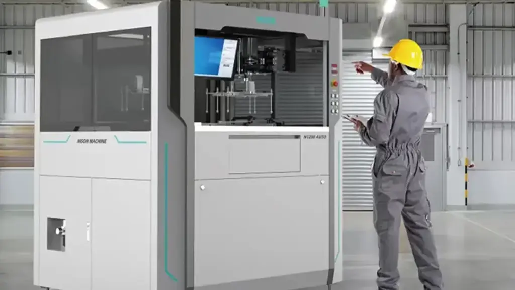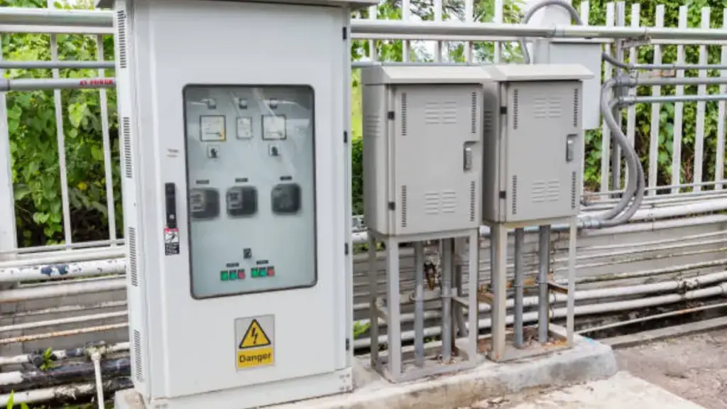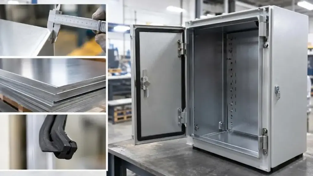
La progettazione della lamiera è un passaggio preliminare cruciale nella lavorazione di chassis hardware personalizzati, custodie per apparecchiature, e particolari in lamiera di precisione. La razionalità del design determina direttamente la resa di lavorazione del prodotto, precisione di assemblaggio, qualità dell'apparenza, ciclo produttivo, e costo di produzione.
La maggior parte delle rilavorazioni della lavorazione della lamiera, deviazioni dimensionali, errori di assemblaggio, e i difetti estetici non sono radicati nei processi di produzione, ma piuttosto nel fatto che la progettazione iniziale non riesce a soddisfare le caratteristiche della lavorazione della lamiera e ignora le limitazioni del processo.
SHIJIE, come fabbrica di custodie hardware personalizzate professionali, si concentra su scenari di produzione di massa per hardware personalizzato. Abbiamo riassunto sette sfide comuni nella progettazione della lamiera nel settore, combinato con la nostra esperienza nella produzione in serie di telai, recinzioni, e particolari in lamiera di precisione, fornire una modellazione del flusso di progettazione direttamente implementabile (DFM) soluzioni di ottimizzazione, offrendo riferimenti standardizzati per i progettisti strutturali, ingegneri degli acquisti, e produttori di elaborazione hardware.
Sfide relative al ritorno elastico di piegatura della lamiera e alla deviazione dimensionale
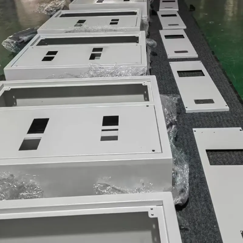
Sfida di progettazione fondamentale
Il ritorno elastico in flessione è il problema più comune nella progettazione della lamiera. Materiali diversi, spessori della lamiera, angoli di piegatura, e le lunghezze di piegatura produrranno vari gradi di ritorno elastico, con acciaio inossidabile e alluminio ad alta durezza che presentano un ritorno elastico particolarmente pronunciato.
La maggior parte dei progettisti utilizza direttamente i coefficienti di flessione predefiniti del software senza calibrarli insieme ai parametri delle apparecchiature di fabbrica. Ciò porta a discrepanze significative tra le dimensioni nei disegni 3D e i prodotti finiti effettivi, spesso causando problemi come angoli eccessivi, dimensioni esterne fuori tolleranza, e articolazioni allentate. Le deviazioni possono arrivare fino a ±0,5 mm, e l'errore cumulativo dopo la produzione di massa incide gravemente sulla precisione dell'assemblaggio.
Inoltre, design irragionevole del raggio di curvatura interno: un raggio troppo piccolo provoca facilmente stiramenti e fessurazioni della lamiera, mentre un raggio troppo grande occupa lo spazio di assemblaggio e influisce sull'uniformità dell'aspetto.
Soluzione
Stabilire una libreria di coefficienti di flessione specifica per la fabbrica, abbandonando i parametri predefiniti del software generale. Basato su diversi materiali come l'acciaio laminato a freddo, acciaio inossidabile, e lega di alluminio, e combinato con la misurazione e la calibrazione effettive dei dati sul ritorno elastico in base allo spessore della lamiera e alle specifiche della scanalatura a V di piegatura, compensare in anticipo il margine di ritorno elastico nel disegno spiegato, controllare le deviazioni dimensionali dalla fonte.
Standardizzare il design del raggio di curvatura interno, seguendo le specifiche standard del settore: per lamiere ordinarie, il raggio di curvatura interno deve essere ≥0,5 volte lo spessore del materiale; per acciaio inossidabile duro e alluminio aerospaziale, il raggio di curvatura interno deve essere ≥ 1 volta lo spessore del materiale, eliminando il problema delle fessurazioni dovute alla flessione a piccolo raggio.
Per pezzi piegati di grandi dimensioni, nervature di rinforzo e nervature di pressione vengono aggiunte all'area di piegatura per sopprimere efficacemente la deformazione del ritorno elastico della lamiera, migliorare la planarità della superficie dopo la piegatura, e garantire la coerenza dimensionale dei prodotti in lotti.
Problemi di deformazione del foro e rottura della filettatura nell'area di piegatura
Sfide di progettazione fondamentali
Nel design di molti chassis e scocche in lamiera, fori per le viti, fori di posizionamento, e i fori di dissipazione del calore sono troppo vicini alla linea di piegatura, un errore di progettazione frequente.
Durante il processo di piegatura, la lamiera nella zona di piegatura viene stirata e compressa, causando una deformazione ellittica e uno spostamento del diametro dei fori adiacenti. I fori svasati e i fori filettati sono soggetti a sfilacciamenti e guasti, con conseguente scarto del pezzo.
Allo stesso tempo, se la distanza tra i fori adiacenti è troppo piccola, rottura dello stampo, bave di foro, ed è probabile che si verifichi il collasso della lamiera durante lo stampaggio, aumentando significativamente il tasso di difetti di elaborazione.
Soluzione
Impostare distanze di sicurezza standardizzate per le posizioni dei fori. La distanza minima tra il bordo del foro e la linea di piegatura è ≥ 2 volte lo spessore della lamiera + 0.5mm, evitando rigorosamente la zona di deformazione di flessione ed eliminando i problemi di deformazione del foro fin dalla fase di progettazione.
Ottimizzare le fasi di elaborazione per l'adattamento del progetto. Se i limiti strutturali impediscono la regolazione dei fori, adottare uno standardizzato “piegandosi prima, punzonatura e poi toccando” processo per sostituire il tradizionale metodo di punzonatura e piegatura, risolvendo completamente i problemi di deformazione dell'allungamento del foro e di cedimento del filo.
Standardizzare il design della spaziatura dei fori. La distanza dal bordo tra fori passanti adiacenti deve essere ≥ 1,5 volte lo spessore del materiale. Per strutture con spaziatura insufficiente, utilizzare lo stampaggio a griglia skip e l'elaborazione passo-passo per evitare danni allo stampo e deformazione della lamiera, garantendo la precisione del foro.
Sfide di scarsa planarità e facile distorsione nelle parti in lamiera a pareti sottili
Sfide di progettazione fondamentali
Lamiera a pareti sottili (spessore ≤2mm) è ampiamente utilizzato nei telai elettronici leggeri e negli alloggiamenti delle apparecchiature. Questi pezzi hanno una scarsa rigidità della lamiera, e dopo il taglio laser, flessione, saldatura, e trattamento superficiale, sono soggetti a irregolarità superficiali, distorsione, e deformazione.
La maggior parte dei progettisti si affida esclusivamente all'aumento dello spessore della lamiera per migliorare la planarità, aumentando direttamente i costi dei materiali e il peso del prodotto, violando i requisiti di progettazione leggera.
La lamiera piana senza strutture di rinforzo determina una planarità incoerente dopo la lavorazione in batch, portando a spazi vuoti e deformazioni dopo l'assemblaggio.
Soluzione
Sostituire la lamiera ispessita con rinforzi strutturali. In ampie aree di lastre piane a pareti sottili, progettare razionalmente le nervature di rotolamento, protuberanze sollevate, scanalature, e flange per rinforzare la struttura. Ciò migliora significativamente la rigidità della lamiera senza aumentare lo spessore del materiale, sopprimendo efficacemente la deformazione superficiale.
Ottimizzare la progettazione della saldatura. Abbandonare a lungo, saldature continue e adottare segmentate, saldatura a punti sfalsati per ridurre l'apporto termico di saldatura ed evitare temperature elevate localizzate che potrebbero causare distorsioni della lamiera. Le posizioni di saldatura dovrebbero essere il più vicino possibile all'asse neutro della lamiera per ridurre lo stress di flessione causato dalla contrazione di raffreddamento.
Seguire un processo di livellamento. Consentire una leggera correzione della planarità durante la progettazione. Dopo l'elaborazione, utilizzare apparecchiature di livellamento di precisione per garantire la precisione planare del guscio e dei pannelli a pareti sottili.
Sfide relative alla piegatura e alle interferenze dell'assemblaggio della struttura in lamiera
Sfide di progettazione fondamentali
Nella progettazione di complessi telai multipiega e gusci di forma irregolare, è probabile che si verifichino interferenze di flessione e problemi di disallineamento del gruppo. I progettisti spesso si concentrano solo sull'effetto di assemblaggio statico del modello 3D, trascurando la corsa dinamica della lavorazione di piegatura e l'occupazione dello spazio dello stampo, con conseguenti collisioni degli angoli ed espulsione dello stampo durante la piegatura di pezzi multipiega.
Nel frattempo, una progettazione irragionevole degli angoli e degli spazi di piegatura può portare a problemi quali spazi di giunzione eccessivamente grandi, inceppamento agli angoli, e disallineamento dell'assemblaggio, rendendo impossibile il normale montaggio.
Inoltre, gli angoli interni ad angolo retto e l'assenza di smussatura li rendono incompatibili con gli stampi di lavorazione convenzionali, che richiedono la macinazione manuale, che è inefficiente e incoerente.
Soluzioni
Verifica del processo di pre-piegatura. Simulare la sequenza completa di piegatura e la corsa dello stampo durante la fase di progettazione. Evitare preventivamente le aree di interferenza per strutture multipiega e di forma irregolare, ottimizzando la disposizione della lunghezza e dell'angolo dei bordi piegati.
Design standardizzato dello spazio angolare. Riservare spazi di processo uniformi nelle posizioni angolari del guscio del telaio, e progettare in modo uniforme smussi di processo standard per gli angoli interni, adattamento alla lavorazione di stampi di piegatura CNC. Elimina i problemi di inceppamenti e interferenze, eliminando la necessità di rettifica manuale secondaria.
Le complesse strutture a strati adottano un design diviso. Suddividere la struttura di interferenza integrata in una struttura di giunzione multicomponente. Fissare con viti e rivetti, bilanciare resistenza strutturale e fattibilità della lavorazione, riducendo la difficoltà della produzione di massa.
Sfide legate all'imbutitura profonda e allo spessore irregolare delle pareti nella formatura convessa e concava
Sfide di progettazione fondamentali
Telaio in lamiera con zone rientranti, rigonfiamenti in rilievo, e le scanalature profonde spesso utilizzano la formatura per imbutitura profonda per le posizioni dei pulsanti e dell'interfaccia.
Molti progetti non riescono a rispettare i limiti di disegno della lamiera, con conseguente eccessiva profondità di disegno, larghezza dell'angolo insufficiente, e larghezza dell'area di disegno incoerente. Ciò porta a un'imbutitura irregolare della lamiera durante il processo di formatura, causando difetti come screpolature dei bordi, assottigliamento dello spessore delle pareti, graffi superficiali, e crollare.
Soprattutto per materiali come leghe di alluminio e acciaio inossidabile, che hanno scarsa duttilità, progetti di disegni impropri determinano tassi di scarto estremamente elevati, rendendo impossibile la produzione di massa.
Soluzioni
Abbina rigorosamente i parametri del processo di disegno, garantendo che la profondità di disegno sia compatibile con lo spessore del materiale e il raggio dell'angolo. Utilizzare grandi transizioni arrotondate per disegnare gli angoli, evitando angoli retti acuti, distribuire uniformemente lo stress di disegno, e prevenendo la concentrazione di stress localizzati e le fessurazioni.
Ottimizza il design in base a materiali differenziati. La profondità di imbutitura può essere opportunamente aumentata per l'acciaio laminato a freddo, riducendo al contempo la profondità di imbutitura unica per acciaio inossidabile e leghe di alluminio. Per strutture ultra profonde, utilizzare un processo di trafilatura e formatura passo-passo in due fasi per garantire uno spessore uniforme della parete.
Lasciare spazio attorno all'area di allungamento per consentire futuri aggiustamenti del processo, evitare che bordi e fori siano troppo vicini all'area di stiro per evitare deformazioni e disallineamenti dei fori durante la formatura.
Sfide nell'adattamento delle strutture in lamiera ai processi di trattamento superficiale
Sfide di progettazione fondamentali
La progettazione della struttura in lamiera non è integrata con successivi processi di trattamento superficiale (anodizzazione, spruzzatura, elettroforesi, zincatura), portando ad un aspetto scadente del prodotto finito e ad una protezione inadeguata.
Un chiuso, il design a cavità sigillata può causare accumulo di liquidi e gas durante la spruzzatura e l'elettroforesi, con conseguente formazione di bolle sulla vernice, corre, e aree mancate. Piccole scanalature e strette fessure, se non adeguatamente levigato o sabbiato, o se il pretrattamento è incompleto, può facilmente portare successivamente alla scrostatura della vernice e alla ruggine. I materiali misti non possono essere standardizzati per il trattamento superficiale, con conseguenti differenze di colore e differenze di potenziale di corrosione.
Soluzioni
Riservare i buchi del processo, prese d'aria, e fori di drenaggio nella struttura della cavità per garantire il flusso del liquido e lo scarico del gas durante la spruzzatura e l'elettroforesi, prevenendo l'accumulo di liquidi, vesciche, e aree mancate, e migliorare l'uniformità del rivestimento.
Semplifica strutture complesse come fessure strette e scanalature profonde per garantire una copertura completa durante il pretrattamento di molatura e sabbiatura, migliorando l'adesione del rivestimento e prevenendo la successiva scrostatura e corrosione della vernice.
Standardizzare i materiali del pezzo in lavorazione per evitare di mescolare più materiali per la stessa parte in lamiera. Abbina ogni parte a un unico processo di trattamento superficiale per eliminare le differenze di colore e la corrosione elettrochimica, migliorando l’aspetto del prodotto e la consistenza protettiva.
Problemi di scarsa intercambiabilità e tolleranze accumulate nelle parti in lamiera in lotti
Sfide di progettazione fondamentali
Nella progettazione di chassis personalizzati e gusci di apparecchiature batch, la caotica marcatura della tolleranza e la mancanza di un punto di riferimento unificato sono le sfide fondamentali nella produzione di massa. Molteplici tolleranze sovrapposte e l'assenza di un punto di riferimento per il posizionamento possono far sì che i singoli pezzi soddisfino gli standard dimensionali.
Tuttavia, gli errori accumulati dopo l'assemblaggio di più parti sono troppo grandi, portando a problemi come viti disallineate, spazi irregolari tra i pannelli, e l'assemblaggio sciolto dell'intera macchina. Ciò si traduce in un'intercambiabilità estremamente scarsa dei prodotti in lotti e in costi di assemblaggio post-vendita estremamente elevati.
Soluzioni
Standardizzare i benchmark di progettazione. Tutte le dimensioni critiche dell'assieme e le dimensioni dei fori devono essere contrassegnate in base allo stesso bordo e alla stessa superficie di riferimento per evitare l'accumulo di tolleranze causato da più parametri di riferimento.
Assegnare ragionevolmente gli intervalli di tolleranza, tolleranze di serraggio per l'aspetto e le dimensioni di accoppiamento. Ridurre moderatamente le tolleranze per le quote libere non critiche, riducendo le difficoltà di lavorazione e i costi di produzione garantendo al tempo stesso la precisione dell’assemblaggio.
Standardizzare le strutture di posizionamento, aggiunta uniforme di perni di posizionamento e fessure di posizionamento alle parti in lamiera dei lotti per ridurre gli errori di assemblaggio manuale e migliorare l'intercambiabilità del prodotto e la coerenza dei lotti.
Considerazioni finali
La sfida principale di progettazione della lamiera sta nel bilanciare l’estetica strutturale, requisiti di assemblaggio, e tecnologia di elaborazione. Sette problemi principali: la flessione del ritorno elastico, deformazione del foro, deformazione delle pareti sottili, interferenza di elaborazione, formando fessurazioni, compatibilità del processo, e accumulo di tolleranza: copertura 90% di scenari di rilavorazione nella lavorazione di chassis in lamiera e custodie hardware.
Attraverso l'ottimizzazione del pre-processo (DFM), progettazione di parametri standardizzati, e adattamento strutturale ai processi di produzione di massa, i tassi di difetti nella lavorazione della lamiera possono essere efficacemente ridotti, cicli produttivi abbreviati, e costi di produzione controllati.
Contemporaneamente, la precisione, aspetto, e la stabilità dei lotti dei prodotti in lamiera può essere notevolmente migliorata, adattandosi alle esigenze di lavorazione della lamiera personalizzata di fascia alta del settore commerciale, industriale, e apparecchiature elettroniche.